My first AR App: ThingstAR

ThingstAR App Icon

ThingstAR App Icon

It has been some time since my last post, but I have a good excuse: I made a new app. And it is already on the Apple App Store 🎉

Since ARKit was released in 2017 I always wanted to create an AR app. But it should at least be useful in any way and not only showcase the AR functionality. As a 3D print hobbyist, I am a big fan of Thingiverse, a platform to share your 3D print projects and models. But you often don’t recognize all the details of a 3D model before slicing or even 3D printing. So it seemed almost obvious to present the 3D models in AR, allowing you to inspect them from every angle.

So I developed “ThingstAR”, an iPad AR app to explore Thingiverse. You can browse by lists or a search term, experience the projects in detail and place the 3D print models using AR. Manipulate the model as you like (e.g. scale, move or change color) and even share it as a usdz file with other iOS users.

I also added some extra features to make this a well rounded app. To name a few:

  • Bookmarks. You can bookmark your favorite projects during browsing and easily access and manage your bookmarks via the “quick access menu” a.k.a. “the boat button”.

  • Size and Orientation optimized. There are basically three different iPad sizes out there, which are used in portrait or landscape. I specifically optimized the app to adapt to all of these situations.

  • Light and Dark Mode. Ok this feature is nowadays more of a must have for new apps. But maybe nice to know as a fellow “everything dark” user.

To get a better understanding of the app, I added some screenshots:

If you‘re interested, you may want to take a look at the App Website or even check it out on the Apple App Store.

Let me know if you have any feedback, feature requests or just some nice words 😉

New Project: RibbaLight5 - A native HomeKit lamp using an ESP8266

The Problem

Home automation can be a very complex thing. And as a maker you can already integrate many different gadgets into your home. But when it comes to HomeKit, the apple universe regarding home automation, the most common way is to add Home Assistant (or similar) on a Raspberry Pi to act as the HomeKit broker. The lamps, sensors, a.s.o. then only “talk” to the broker using MQTT. This allows you to create pretty complex scenarios and automations, but it also forces you to add an additional single point of failure into your setup, which can reduce the overall reliability. I always kept back from this solution, as I don’t want to power and service the Raspberry Pi.

The Solution

I then found a github respository which allows you to create native HomeKit devices, running FreeRTOS on an ESP8266 or even an ESP32. You may only need the demo repository, which contains all of the demo code, many different examples and the build instructions. The development setup is a bit complex, but the documentation in the Wiki section worked perfectly for me (using the docker stack on a Mac). The idea is basically to write your own gadget code, which then runs as a Task on FreeRTOS, a MIT licensed realtime operating system. There are already a lot of examples in the repository, like for all sorts of sonoff devices, but it is also pretty easy to create your own task for your IoT device by taking a look at the example code.

Another HomeKit lamp

This sounded alluring, so now I only needed a use case to build such a thing. As I have quite a history with the WS28XX family of LED strips, meaning having them laying around, it seemed obvious to build a simple lamp. Also obvious was the choice of the enclosure, the IKEA RIBBA picture frame (the 23cm by 23cm version, white. currently only available in bamboo). It has some great features for DIY projects, as its cheap, offers enough space for the electronics and has a simple yet stylish design. For the ESP part, I wanted to use a cheap development board allowing me to program and power the board via USB but also to power the LEDs without a separate power circuit. Fortunately the NodeMCU v3 offers all those features, as it has a 5V output pin and is less than 7€ on amazon. And as we now know, we should use a 5V led strip, in my case a WS2812B RGB LED strip with 60 leds per meter. This fits easily 144 leds inside the picture frame (12 rows, 12 leds each). So I cut the strip to segments of 12 leds and simply connected the wires on the end of each row to the beginning of the next row, a.s.o. But there is one speciality. Some led strips have such high resistance (per meter), that the leds further away from the power input get darker. To prevent this I simply fed the power into the strip on three different positions. This reduces the maximum resistance to a third, each line only powering four rows of leds.

RibbaLight_LEDStrip.jpeg

Then I only had to connect the strip to the NodeMCU. Power to power (Ground and VV) and data to RX (the port is fixed inside the software as it is using hardware i2s). And the hardware build was finished.

As you can see the enclosure is almost unchanged. I just added a cutout for the NodeMCU, giving it more space to breathe and added a notch to the bottom of the frame for the usb power cable. And finally to create a more defuse light, so you can’t see the single leds, I put a frosted film behind the front glass. Done.

The Software

In my case the demo project “led_strip” almost did the trick, I just needed set my wifi credentials, change the number of leds and be aware of the wiring. Ok, I also overclocked the ESP to 160MHz, as in my opinion this should be the default mode for the ESP8266. Although the initial setup was a bit scary, building and flashing the software were just two simple commands from the documentation.

PAIRING

qrcode-example.png

Now you have a new HomeKit device and need to add it your home setup. There are different ways to achieve this, but the easiest might be using HomeKit QR Codes. You initially set the accessory password and setup id inside your code and use those to create a HomeKit compatible QR code to add the device inside the home app. A script to create those codes is also available in the main repository, you can see the result on the right.

So if done right, the setup process should be as simple as: Open the Home app, tap add device, scan QR code. And the new device should be added to your home. As our device is not apple certified you will get a warning, but you can simply ignore it.

You can alternatively also enter the device password manually inside the home app, as you pair the device only very few times, this is also not too much of a hassle.

USAGE

Sorry, but the light conditions make this hard to catch.

Sorry, but the light conditions make this hard to catch.

Now that the lamp is available inside the Home app you can also use HomeKit automation. In my case the lamp was meant as a corridor light switched by a motion sensor. It should actually also be possible to make your own motion sensor based on this stack, but I used a Philips Hue Motion Sensor instead. It is a really great little device, as it also monitors brightness and temperature and runs forever on 2 AAA batteries. This also requires a Hue Bridge in your environment, but you’ll need it anyway if you want to integrate any Philips Hue or IKEA TRÅDFRI device s.

By default the “led_strip” demo project already supports switching the light on and off and setting the color, brightness and saturation, but you can add and remove “characteristics”, as they’re called, as you like.

If we talk brightness, this is definitely not meant as the only light for a room. It is more a HomeKit mood light, which supports scenes and automation, maybe best comparable to a Philips Hue Bloom (around 60€ retail). I then measured the power usage on standby and on max brightness. So it seems the light strip draws around 8 Watts of power and the NodeMCU itself takes additional 0.8 Watts. So if the lamp is permanently connected to power, even when switched off, it will add to your power bill, but it is so minimal, that it won’t make you poor. Just to keep that in mind.

Almost done

So everything is was working, but if the wifi password changes, we would have to change the password in code, recompile and flash again. This is not very convenient, but there also is a ready made solution to this. The example project “wifi_config” offers a process for wifi configuration similar to my coffeePID solution. So if no wifi credentials are stored the esp starts its own wifi, you can then select the wifi and enter the credentials.

Pro / Con List

To close up this project, I want to give a retrospective in form of a pro/con-list. It shows why I like this project so much...

Pros:

  • native HomeKit support

  • pretty cheap

  • low build barrier

  • no need to recompile on wifi credentials change

Cons:

  • kind of complex development setup

CoffeePID: optimizations

As we saw in the last post (CoffeePID: the build) the project integration was quite successful. Unfortunately the resulting temperature curve is not what I was hoping for. But to be able to fix this issue, we first need to understand the problem a bit better. The target temperature was set to 97°C, so the heater stopped at that limit. So lets start taking a closer look at that first measurement:

Initial heatup of the Gaggia Classic with CoffeePID

Initial heatup of the Gaggia Classic with CoffeePID

So what can we take away from this?

  • It seems that the heater is quite powerful, as it quickly manages reheating the boiler at falling temperatures. This means it should be possible to keep the temperature pretty stable, or at least keep the “underswing” of the temperature at a minimum.

  • The system is very inert. After only 2 seconds of heating the measured temperature is still increasing for more than 5 seconds. This means that we have to be more careful with (re-)heating phases and that it may be a good idea to add some delay after heating, before we take the next measurement and react on it.

  • Fun fact: We can clearly see that the frequency of the oscillation decreases over time, as the heat takes longer to dissipate and therefore increasing the cool down duration. So we basically know the state of the system (all components cold or heated up) by just taking a look at that frequency.

  • The last thing to state is, that the current heating strategy is crap. After reaching a “stable” system the temperature was still swinging between -2°C and +7°C around the target value.

Note: This curve is also exactly what we would expect from the static thermostat originally used. It just switches the heater at a “fixed” temperature. At this point I just digitized the original problem. Yay!

Let’s fix this

At this point I already tried at least 3 different strategies to optimize the temperature regulation and I am somehow sure that I’m not done. But this was the first real promising attempt:

Based on the measured temperature we need to calculate the duration to heat up to the target temperature. This will be a proportional factor, increasing the heating duration proportional to the temperature delta. For example heating double as long to heat up +20°C compared to +10°C. But this part is not enough, as it would never heat at or above the target temperature, but this may be a good idea on a quickly falling temperature. So we need a history of the temperature readings and calculate the incline. If the temperature is rapidly falling we need to heat longer to achieve the same heating effect as if the temperature was raising. We will later only have to find the constants needed to incorporate the formula to describe this system. So the formula simply looks like:

t = A * ΔT + B * a

A and B are the constants and a is the incline of the temperature curve, which is measured over the last 5 values in history. We can even simplify this by directly using the temperature delta as the incline. So the formula reads: the time to heat up to a specific temperature is equal to the sum of a constant times the temperature delta to overcome and a constant times the temperature delta of the last 5 values. It is obvious that B has to be a negative value here, as a temperature decrease (negative delta) should lead to a larger heating duration. I tested this a lot with my Gaggia Classic on my desk close to my computer and I came to these magic values:

A = 620, B = -8600

I’m sorry that those values most likely won’t work for you out of the box, as these are very system specific and timing critical. Even adding or removing Serial.println()-statements in the code will change the timing and therefore you have to optimize these values again. As I said, I spent some time doing this. But the values are actually not that magical, as we need a duration in milli seconds the heater should run. So A is just the time the heater runs to heat up the water 1°C. Whereas B is a more abstract factor which is important for the differential part. The factor can be substantial, e.g. when the current temperature is very close to the target temperature but rapidly falling. The first factor will then be close to zero, so the heating duration has to come from this part. So with my current values, if the temperature fell 0.25°C in the past, we would add 2150 ms to the heating duration. Reading these values the first time in written form, I have to say that it sounds really plausible. And the results were also pretty promising:

Optimized heatup of CoffeePID in my Gaggia Classic

Optimized heatup of CoffeePID in my Gaggia Classic

We can still see some minor oscillation in the curve, but if you check the y scaling, you will see that the temperature oscillation is less than 1°C in total amplitude.

One more thing

After I finished tweaking the values I was quite happy with the result. But that only lasted till the next day, when I made my first coffee. I realized that the values didn’t work as great in a cold-start scenario. The machine initially needed many heating phases to come close the target temperature although it was designed to “shoot for the target” with every heating phase. This is also plausible in retrospective, as the machine itself needs more “energy” on the first start to heat up all internal components and materials. The simple solution was to change the magic values a bit (A = 1000, B = -9000). This reduced the duration to reach a stable target temperature a lot and after around 10 minutes the system was swung in to less than ±0.3°C.

Conclusion

After using my Gaggia Classic with CoffeePID for some time now, I’m still satisfied. The machine obviously still takes about the same time to heat up completely, but it then manages to keep the temperature very stable. Even after pulling a shot of espresso it recovers pretty quickly. From this point of view I would declare this project successfully finished. Yay!

Outlook

It took me some time to write all these findings down and while I was working silently, a tweet and a github pull request reached me. A reader of this blog, built a CoffeePID himself and made quite some additions to the source code. This is so great and it promises us many features that I wanted to add in the future, namely:

  • Over-The-Air updating

  • a “real” PID-control

  • a PID-autotuner

I am currently in the state of checking this pull request and hope to come back to you pretty soon. Thanks for reading till the end, if you did ;) Stay tuned.

Other parts of this series:

CoffeePID: the build

Finally it’s time to put the CoffeePID to work. I have testet the software and hardware outside the Gaggia Classic and am very confident, that the integration will not be that big of a deal. Let’s see how this turns out… But first a little service and security advice:

Be aware, that the machine is internally working with 230V (or 110V, depending, where you are). So working on a powered machine can be very dangerous! This is why you should ALWAYS disconnect the power cable in the back BEFORE opening the machine and start fiddling with its internals.

Placement

The first time I took a closer look inside the machine to plan the component placement I was a bit disappointed, as the first plan to simply screw the SSR to the slots on the backside the machine didn’t work out. Besides that setback it turned out that the placement should be quite easy. I wanted to place the power supply, the WEMOS and the MAX31865-breakout on a mounting plate and put that on the backside of the machine, right behind the water filling funnel. That funnel makes it a bit tricky and is why I placed the components as close to the bottom as possible. Keeping those parts close together is generally a good idea, so we can use shorter cables and reduce the mess a bit. The SSR will be placed to the left side of the machine, this way it is close to the position of the original thermostat, simplifying wiring. There is also a lot of space below the front panel, but putting the relay there would be too much of a hassle, if you need to access the ports. I fixed the SSR using double sided thermal adhesive tape, this way it can dissipate the heat via the machine body.

The PT1000-element

Obviously I had to find a solution to the fact, that the thermal element is a small cylindrical element and the thermostat it replaces has a male M4 screw thread. But there is a simple fix, I just glued the PT1000-element inside a M4 spacer using thermal adhesive. That way the PT1000 is just a simple drop-in replacement to the current boiler thermostat. At least that is what I thought. Unfortunately if you only remove the top plate / water funnel, it is very difficult to screw in the PT1000. I only managed this with the help of my wife and a lot of patience. For the not so patient type it is a good idea to unscrew the boiler from the machine to put the new thermoelement in place.

Wiring

As I already had a look at wiring schematics of the machine, I was confident, that the integration should be not too hard. And as it turns out the modifications are really minimal. Starting at the thermostat, it is initially wired to the main power switch at the front and to the heater (and heating light). As this is now the job of the SSR (switching the heater), I simply connected the thermostat wires to the relay. Now there is only one thing missing: the power supply for the CoffeePID. As I want the CoffeePID to switch on with the machine, I need one wire from the just connected “input-wire” of the relay, which is switched by the main switch in the front and one wire that I can easily grab from the back.

LAST MINUTE CHANGES

During the integration planning I realized one possible issue. I want to be able to connect to the ESP (e.g. via USB serial monitor) after the CoffeePID has been integrated, also when the coffee machine is running. But it was planned to permanently connect the power supply to the power switch, so the ESP would be powered from the power supply and via USB, if connected. It is generally not advised to run a microcontroller board this way, as the power distribution on most boards is not designed for this mode and may damage the board permanently. To prevent this I simply added a connector to the AC side of the power supply, this way I can disconnect the power when connecting to the Wemos via USB. This is how the final build looks like and how I placed it in the Gaggia Classic.

POWER ON

As noted before, the temperature regulation is currently very simple, but I wanted to see the results first before tweaking the code. So I used the serial plotter of the Arduino IDE to create a chart of the initial heat up:

Initial temperature curve of CoffeePID in my Gaggia Classic

I am actually pretty ambivalent about this first graph. But what was I expecting? On the one hand it clearly shows that the build is working as planned. Below the target temperature the ESP switches the relay and therefore the heater on. Above the target temperature the relay is switched off, letting the water cool down. Unfortunately this is a pretty inert system leading to substantial overshoot and a quite large oscillation. Regarding temperature stability this is not what I was looking for, but I already indicated, that this might not be the final implementation. And with this new task of optimizing the temperature regulation, it seems that this will not be the last post in this series.

I hope you enjoyed the journey so far and stay with me on my way to a better coffee experience.

Other parts of this series:

CoffeePID: the web interface

This part was the most interesting one yet. I wanted to create a real simple user interface, so I can see the current temperature and if the machine is currently heating. This could be done writing all from scratch, but to make this more convenient I included Bootstrap 4 and jQuery to the page. As the libraries are also needed in access point mode, I couldn’t load them from a CDN and had to serve them from the ESP. 159 KB for BS4 and 88 KB for jQuery may not sound very much, but already have a very noticeable impact on loading time. More on that later.

The Frontend

As I wanted to keep this really simple, the main page only shows the current temperature of the boiler and an indicator if it is heating. And then of course there is the settings page to set the target temperature and change the wifi settings. I also added some convenience functions for setting up the wifi connection, this way I can see the signal strength of the received wifi networks.

After initial load of the site, the content is updated via ajax calls. Changing the settings or rebooting the ESP is also implemented via additional ajax endpoints.

Although the website is not complex at all, there was quite a some potential to optimize it for the ESP8266. This is mainly due to the poor data transfer rate you get in real life situations, especially compared to current computers and smartphones. But if the web server and -site are implemented correctly the result can be pretty snappy. Which brings me to the next point:

Optimize, Optimize, Optimize

I spent quite some time on this step, as everything should be as fast as possible, so I optimized the web server and website for minimal transfer size and maximum performance. To achieve this I

  • optimized html files using preload, async and defer

  • reduced overall file count (reducing the number of requests) - some people might think that combining files is a bad idea, because this way the files could not be loaded in parallel. But the ESP8266 doesn’t transfer the files over WiFi in parallel; in this case it’s a good idea to reduce the total number of requests to eliminate server processing and latencies from those extra calls.

  • purged all unused css from css-files (using purgecss) - in my case this reduces the size of the Bootstrap library from 159KB to 34KB 🎉

  • minified all js and css files

  • optimized all image files

  • compressed ALL files (assuring all files are transferred gzipped to the client)

  • optimized the critical code path on the server

After all optimizations I ended up at around 135KB transfer size to the client and less than 1 second of initial load time. As all files are cached on the client, all subsequent calls are much faster. Also I want to mention that my background image alone is 62 KB in (compressed) size, so the rest of the site is around 73 KB, which is pretty good.

To make the process of editing the website and prepare it for deployment more comfortable, I added a small shell script (included in the Github repo), which mainly executes all optimization steps on the website. After executing the script, the directory is ready to be copied to the LittleFS.

The ESP can obviously handle much more complex websites, even if the website itself doesn’t fit into the LittleFS area of the flash, you could for example use an SD card breakout to serve your site from a SD card. Also a complex site doesn’t have be slow, it depends a lot on the purpose and content. The optimization steps above can be applied to every website and are especially advised in such a resource constrained environment. But if you don’t need the site to work on access point mode and can assume that the client has an internet connection, you should offload as many resources to “the web” as you can. Fonts, CSS and JS (especially Bootstrap and jQuery) can easily be loaded via CDN and most other assets, like images, should also be loaded from a “real” web server on the internet. Just be sure to check the constraints of your final application before starting to optimize.

But I didn’t “just” optimize the website, I also tested different web servers on the ESP for their performance. That is why I also gave “ESPAsyncWebServer” a try, which works completely asynchronous and should be able to perform a lot better than “ESP8266WebServer” under certain conditions. Unfortunately in our special scenario, it didn’t show any performance improvements at all. This is most likely due to the fact, that there will be (at least most of the time) just one client accessing the web server at a time, so it seems the async implementation can’t really show its potential here. That is why I ended up using the package “ESP8266WebServer”.

The web server

Regarding the implementation of the “ESP8266WebServer” library, there are basically two ways to serve files from LittleFS. You can use sth. like:

This is cool, as it serves all files from the LittleFS-folder “/www/”, sets the cache header and automatically serves a “.gz” version of the requested file if available. So in many cases this is all you need to host a whole website.

But after a lot of testing I decided against the “serveStatic”-way, as it is slightly, but measurable, slower than handling the file serving yourself. This is only logical, as we can optimize the code executed on every request much better to our specific use-case. You can do this by defining handler functions (per route) or even easier, just only define a onNotFound-handler. It will then be called on every unregistered route, so for every file of the website. Our handler then loads the requested file from LittleFS, sets the correct file type and cache headers and serves the file using the “streamFile” functionality.

As we created the website ourself we can take an opportunistic approach in the handler function, therefore we assume all files exist as gzipped version and we can limit the support of file types to the ones used in the project. This way the critical path, meaning the code on the microcontroller that gets executed on every request, can be simplified. Even sorting the file types by frequency of occurrence will have a positive performance impact (although this most likely wont have a noticeable effect).

Finishing touches

Now we have a fast frontend to check our water temperature, but you still have to open a browser and navigate to “http://coffepid.local“. Even if you bookmarked the address, this is not really user friendly. To make this more convenient I added some meta tags to the head of the page and added an app icon, so you can use it as a web app. I don’t have any Android devices around, but on iOS you can easily create a link to a website on your home screen (this is most likely also true for Android, I just can test it). Now I can open the web interface using the app icon on my iPhone or iPad. Cool.

NOT FINISHED AT ALL

After playing around with this once called “sweet solution” of web applications, I reached one limitation. My website was generally based on two files (with additional css and js), a homepage and a settings page. That meant navigating between the sites changes the route in the browser and therefore leaving fullscreen mode of the web application. To overcome this limitation the page had to be served from one file, to implement navigation I used hash routing. It was very interesting to implement this, what is basically a very simple SPA-framework. This is mainly done just using one html file to load all the resources and act as a template and one javascript file managing routing and AJAX calls. I won’t go into the details here, as it would go beyond the scope of this post, but you can take a look into the code over at Github.

This solution works fine, but changing the content of the website is now pretty uncomfortable, as the html content of the site is now dynamically injected as a javascript string (from the file “content.js”). Also for such a minimal web interface using Bootstrap is definitely a bit heavy, but as my CSS skills are quite limited, this was the obvious choice. But if you are a designer / frontend developer and want to help out, feel free to reach out to me. A little help would be really appreciated.

Wrap up

As the hardware setup, “firmware” and frontend are somehow finished, the next step will be the integration into the Gaggia Classic. I will share the details on the build and of course the first results on how the heat up process looks like.

Other parts of this series:

CoffeePID: the software

After I had decided on all the hardware (see here), I was really motivated to get the software part running quickly. I love these kind of projects, as I always learn a lot of new stuff.

But first we need to know how the components are wired together and how they talk to each other. The PT1000 (2-wire) is simply connected via the terminal block to the MAX31865-board, which itself is connected to the ESP8266 using SPI. The SSR can then be controlled by almost any remaining free IO-pin on the ESP. Two little anecdotes regarding this:

  • Somebody taking a look at my final pinout may think: “Why didn’t he just use the SlaveSelect port of the WEMOS D1 mini pro as the ChipSelect port for SPI? This way you can’t use hardware SPI and the wiring is a bit odd.” - I would reply: “Thanks for the hint, but I already tried that. And while SS was connected to CS of the MAX31865, the ESP8266 couldn’t be programmed anymore. This may be related to the fact that the flash of the WEMOS D1 mini pro is itself connected to the ESP8266 via SPI. The funny part is, that this only effected programming, the code was actually running fine using hardware SPI. To fix the programming issue, I simply switched the CS port to another free IO-pin, as I don’t really care for hardware SPI anyway.”

  • Don’t use the port “D4” of the WEMOS to switch the relay. DON’T. Believe me. RealIy really! I actually initially chose that port randomly, but experienced some strange issues during uploading, when the SSR was connected to the ESP. This is simply because D4 is connected to the on-board led, which is switched on multiple times during programming. This meant the SSR was switched multiple times pretty quickly while uploading the firmware, what apparently can lead to problems. I also simply changed to another free port and finally everything is working as intended.

So the setup I ended up with for developing the software looked like this. I’ll redo the wiring later, when I know where and how I want to place the components inside the machine.

Components of CoffeePID (PT1000 bottom left, MAX31865 top left, WEMOS D1 mini pro top right and the Solid-State-Relay bottom right)

Components of CoffeePID (PT1000 bottom left, MAX31865 top left, WEMOS D1 mini pro top right and the Solid-State-Relay bottom right)

But now to the software, really really

First we have to decide on the platform we want to use. I usually use the Arduino environment in most of my ESP8266-projects, as it offers a great ecosystem regarding programming and libraries and has pretty good ESP-support. So there were also libraries for every needed component in this project, like web server, pid, MAX31865, mdns and persistent storage. This will make the coding of those components very lightweight and simple, as you will see later on. Any finally it’s very easy to program the WEMOS D1 using the Arduino IDE.

Before writing any code you need to setup the Arduino environment including all esp8266 stuff (see here). Then you should be able to select your board via the tools menu. And here (in the tools menu) is another quality I like about the ESP8266: You can easily overclock it. It runs on a base clock of 80 MHz, but you can set it to 160 MHz via Tools > CPU Frequency. I run all my ESPs overclocked, for years now, and I never ran into any thermal or power issues. So from my perspective it is totally safe to permanently run these chips on 160 MHz which greatly improves performance.

As it would go beyond the scope of this post, I will not explain every detail of the final code here, but I commented the code quite thoroughly to make it easier to understand what’s happening. The full source code is available at the Github repository, feel free to use and modify it, as you like. Also if you have any issues or questions regarding the code, just create an issue in the repository.

Using the PT1000

Let’s start with the code right at the core functionality: measuring the temperature. As I use a breakout board similar to the Adafruit MAX31865, I can simply use the Adafruit library. And that is quite nice, as Adafruit has always great examples and tutorials (here), so the implementation was a breeze. I just had to install the “Adafruit_MAX31865“ library via the Arduino IDE and the integration of the breakout and measuring the temperature were reduced to just these few lines of code:

Be aware, that there are two different “versions” of the MAX31865 breakout board. The PT100 and the PT1000 version, which only differ in the on-board reference resistor (PT100 -> 430 Ohm, PT1000 -> 4,3 kOhm). I actually had to switch this resistor on my board, which was a bit tricky, as it is a pretty small SMD component.

Integrating the Solid-State-Relay

Next up is switching the relay. As we use a relay that can be triggered with 3,3V TTL-level we just define an output pin and initialize it with “LOW” (meaning the heating being switched off). Then later, depending on the temperature reading, we can switch it on and off as we like.

I actually don’t know yet how I should implement this for best temperature stability / accuracy. Of course it is quite simple to implement a real software PID, but as our controlled variable (switching the SSR) is digital and not analog, I doubt that this will give us an ideal result. It is also a lot of work finding optimal PID parameters preventing a temperature overshoot and reducing the (damped) oscillation around the target value. At this point the firmware simply works as a binary switch, heating below the target temperature and switching off, when it’s reached. I’ll come back to this later, when I can test different heating strategies in real live.

WiFi

Let’s continue with the next part: make it connect to the wifi and start a web server. It was important to me, that the wifi credentials are not hardcoded in any way, so you can change your wifi password without recompiling the software. There is a great project called “WifiManager” (Github repository) that solves the problem for you by implementing a captive portal to enter the wifi credentials. But as the frontend is not very appealing and we want to optimize the process as much as possible, I created my own somehow similar implementation. This is the setup process I came up with:

  1. Check for saved credentials, if there are credentials stored, the ESP will try to connect to the network.

    • On success: the CoffeePID is now reachable in your wifi network.

    • On fail: If no credentials are found or a connect is not possible for more than 20 seconds, the controller starts in access point mode and you can connect to its network.

  2. Now the chip is reachable via any device connected to its network.

The code to connect to a wifi network or create an access point is also pretty straight forward:

The microcontroller is now reachable in the network, but I didn’t want to type the IP address into the browser, so addressing it by name would be great. This can simply be achieved by using mDNS responder (aka: Apple Bonjour) which makes devices announce their name on the network and are therefore discoverable by all other network clients. And again, there is a library for that (named “esp8266_mdns”), reducing the code to:

Great, we now can reach the web server of the ESP8266 at the address “http://coffeepid“ (Depending on the network it may be necessary to append “.local” to the url).

Webserver

As I will go into the details in a later post, let me just show you the basic integration. I used the library “ESP8266WebServer“ (installed via the library manager) to host the website on the microcontroller.

LittleFS

So finally we need to have some kind of internal logic which manages the wifi credentials, being able to persistently store and retrieve them from some kind of memory. The easiest way to store data permanently on a ESP8266 is to use its integrated file system. You can choose between two different filesystems, SPIFFS is the “classic” implementation and generally very lightweight, LittleFS is a pretty new implementation and focused on real directory support and performance. I did a performance comparison and in this scenario LittleFS was much faster for serving the files. And again, using the according Arduino library you can access files with very few code. But how do you write files to the LittleFS area using the Arduino IDE, because we want to write all files needed for the website in this area. There is a plugin for the Arduino IDE which allows you to write all files from a folder named “data” in the project directory (GitHub repository). For security reasons I separated the paths for the configuration file and the web server content, so the web server has no access to the configuration file.

Now we can check for a valid wifi configuration and switch the network mode correspondingly. The controller starts in wifi client mode if there are saved wifi credentials or in access point mode if not. So it’s up to the enduser if you want to use the coffeePID inside your existing wifi network, or if you want it to create its own.

RECAP

So, the ESP8266 is now connecting to the network (or creates its own), can handle local configuration files, measure the temperature and switch the relay. We now “just” need the functionality to set and show the temperature to the user. And as already mentioned, this will be done using a web frontend. But that is definitely a completely different story / post. I will report on my journey of creating and optimizing the frontend soon, so stay tuned…

Other parts of this series:

New Project: CoffeePID - a generic PID controller for coffee machines

Gaggia Classic / Model R9303/11

Gaggia Classic / Model R9303/11

As many people: I love coffee, I would even call myself a coffee enthusiast, owning a Gaggia Classic (R9303/11 to be precise) since 2014. I’m generally very happy with the machine, but there is one specific weak point: the stability of the water temperature, especially during the brewing process.

This is a common issue with many machines, where the water temperature is controlled by a simple fixed temperature thermostat. That’s also the reason why you can find quite a lot DIY projects where coffee machines are upgraded with a PID controlled temperature regulation. There are even kits sold, specifically tailored for many different makes and models. All those projects work basically the same: The boiler / water temperature is measured using some kind of thermo element, a solid-state relay to control the heater and the PID controller itself. Most versions show the current and set temperature on a small seven-segment display. You can set the water temperature via buttons below the display.

Motivation

Unfortunately most projects are either “invasive”, meaning the machine casing needs to be modified and / or live in small extra cases attached to the machine. Some kits are also pretty pricy, the Auber PID Kit for my machine for example is around 200$. So none of the existing solutions would work for me, as I want to preserve the machine (casing) as is, so the project is completely non-destructive and reversible. I also planned to spend a lot less money on the project compared to the ready-made kit.

As I have some experience in the field of microcontrollers, measurement and control, etc. I thought this might actually be a nice little project. So how would I design a solution for the problem? There were the following constraints / guidelines:

  • no case modifications

  • be completely invisible from the outside

  • ease-of-use (no extra startup tasks, just switch on)

But there is actually one aspect that I will ignore at the moment. As I never use the steam function, it is currently not important to me to keep it working. But for those of you who need this, it should actually be no problem to use the steam function with CoffeePID, it’s just not on my todo list for now. It is also very likely that I will come back to this in a later post, so stay tuned. In general I want to note, that this is somehow a first stage of the project. It is very likely that I will change some hardware decisions after I received and tested the whole setup. There is also a lot of potential for other modifications, but I wanted to start with a “minimal” setup. Especially after placing the components inside the machine we will see, if there is any room left to fill. But for now let’s stick to a quite simple setting.

Hardware Choice

WEMOS D1 mini pro V1.1.0

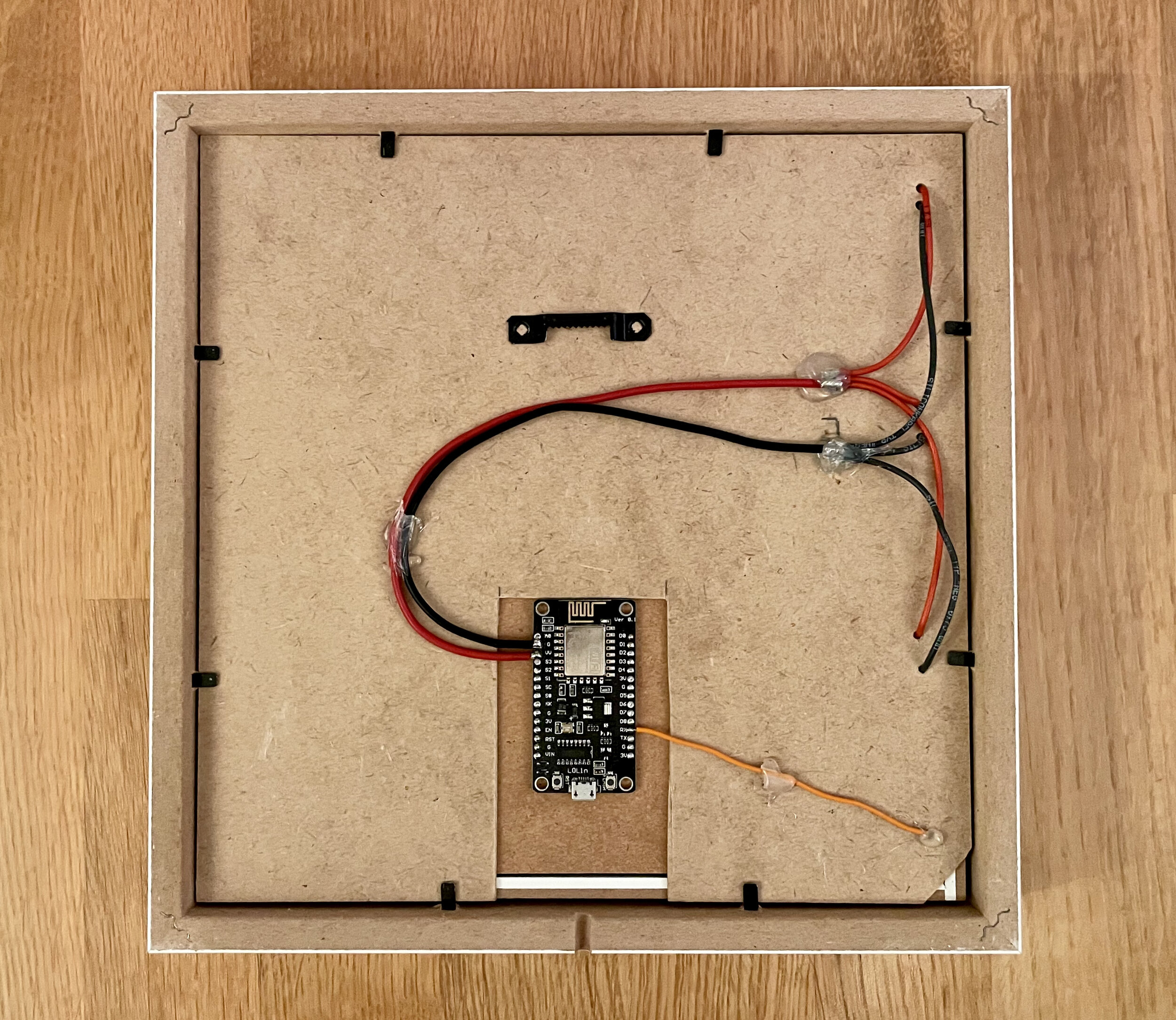
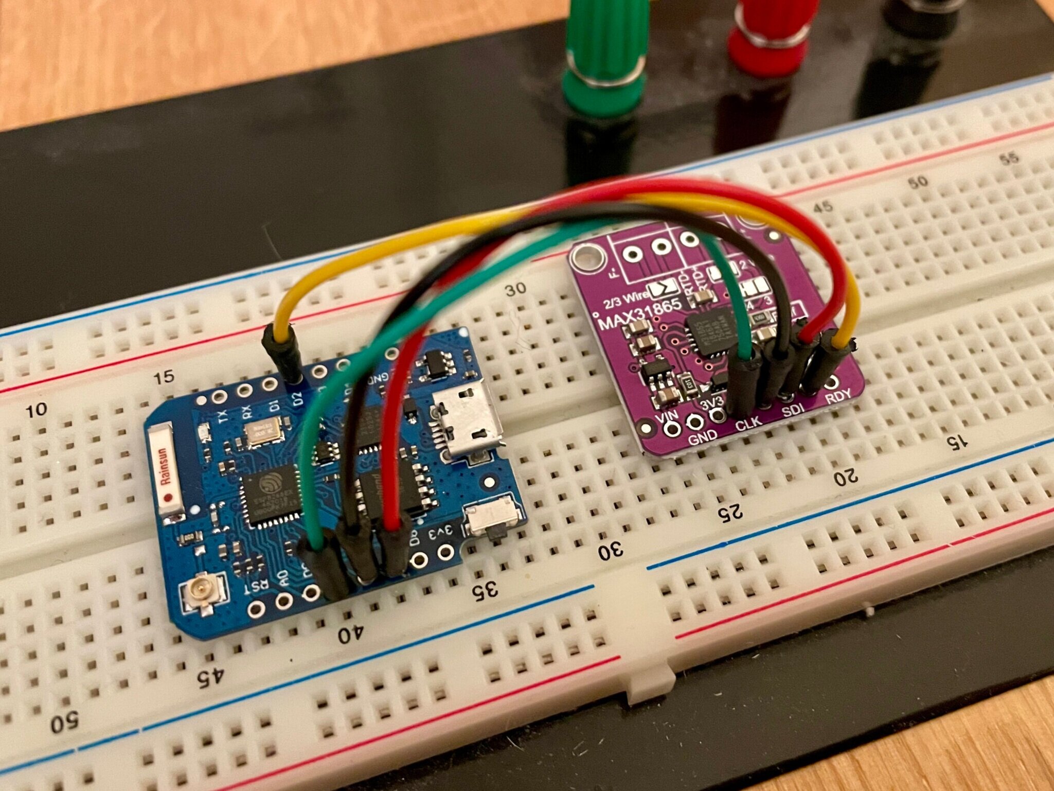
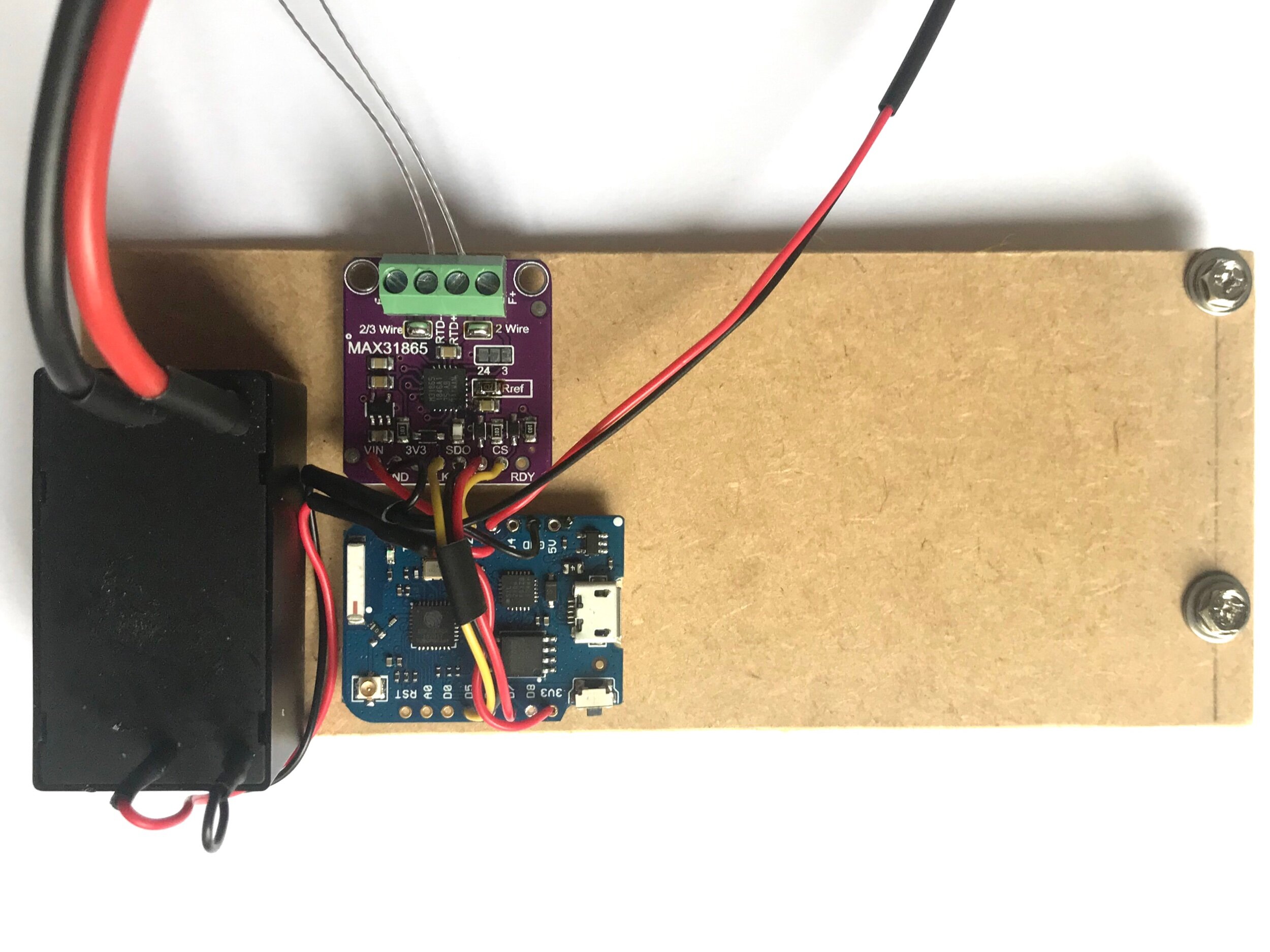
The controller part could be implemented using one of many different microcontrollers available. To keep the complexity of the project low I wanted to use sth. Arduino compatible yet powerful. In other projects the ESP8266 has always been a good friend, so it should cope with this challenge easily. I especially like the WEMOS D1 mini pro board for development and even static use, as it is very compact, can be directly programmed, has enough CPU power, flash and IO and is pretty cheap (around 3€ a piece at AliExpress). It also offers the possibility to connect an external antenna. At this moment I want to have this option as a backup, because I intend to use WiFi functionality of the ESP8266, what is very likely a very bad idea. Putting the chip inside a massive stainless steel case may impact wifi performance, that’s when an external antenna should come in handy.

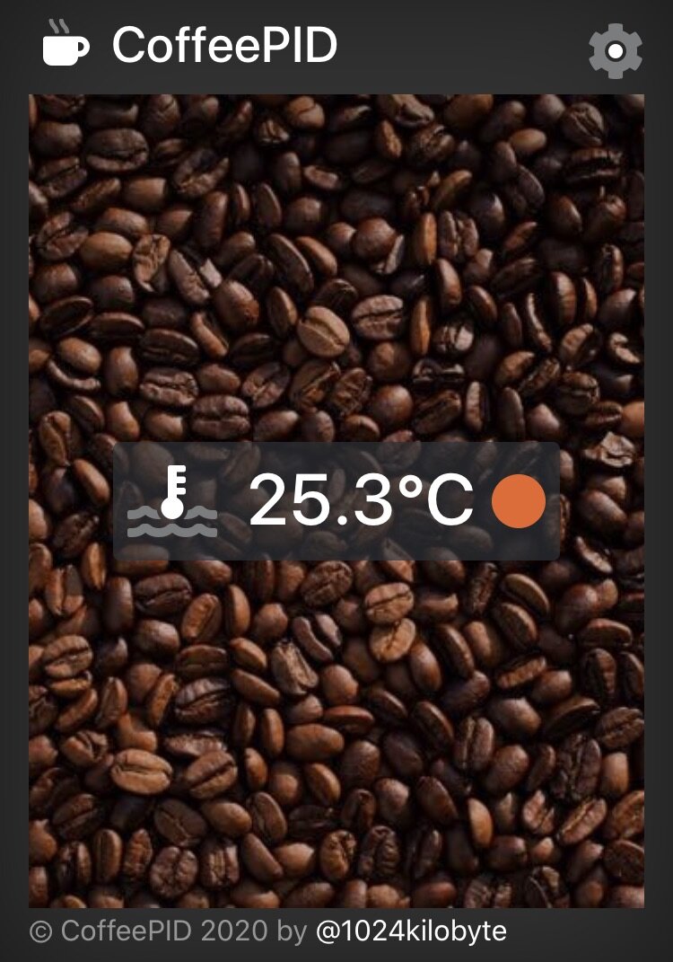
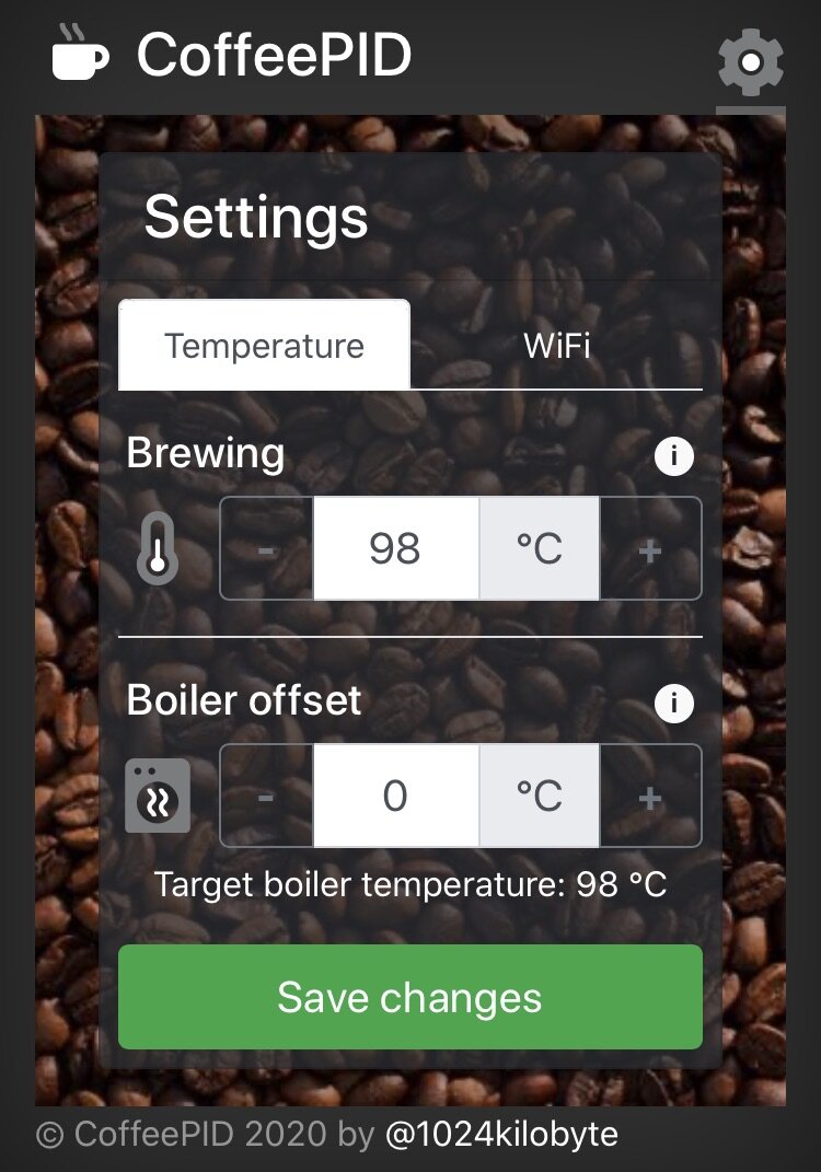
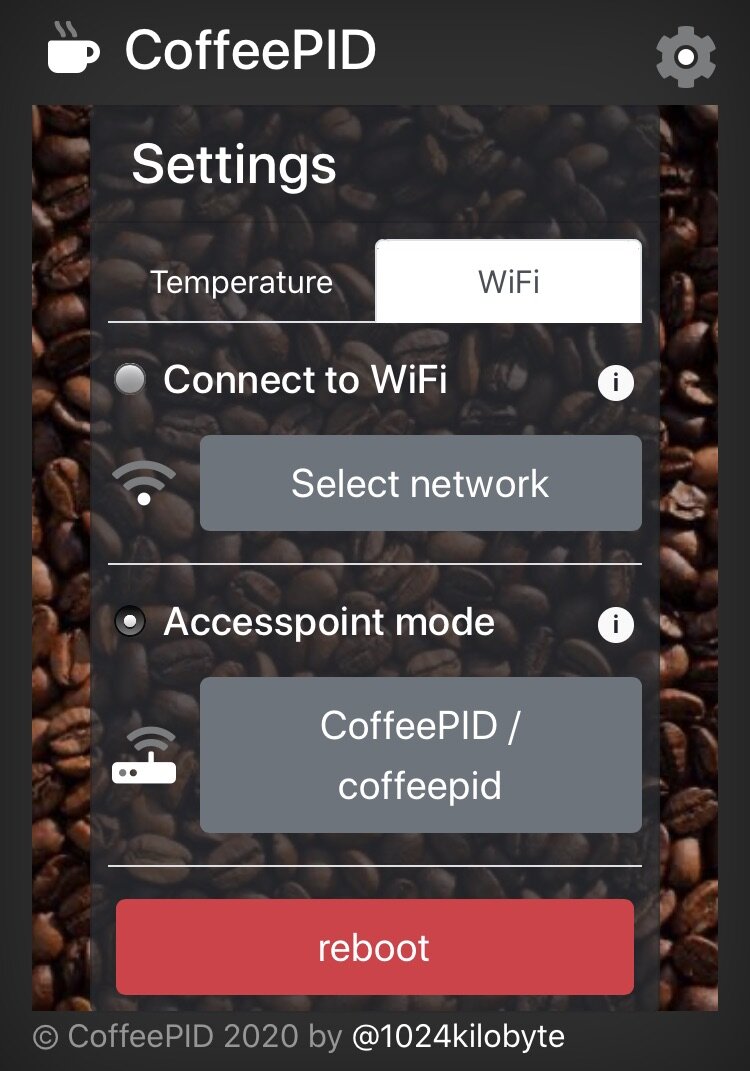
The next decision was on how to set and display the temperature: buttons and a display? But then how about the original look of the machine? I had some doubts about it, but I decided to go with a web interface served via the ESP. It is plenty quick, can act as an access point or as a wifi client, and with some love to the details it should be very easy to use.

As of now, I already have a lot of code running, but I will come back to this later and first complete the list of hardware choices.

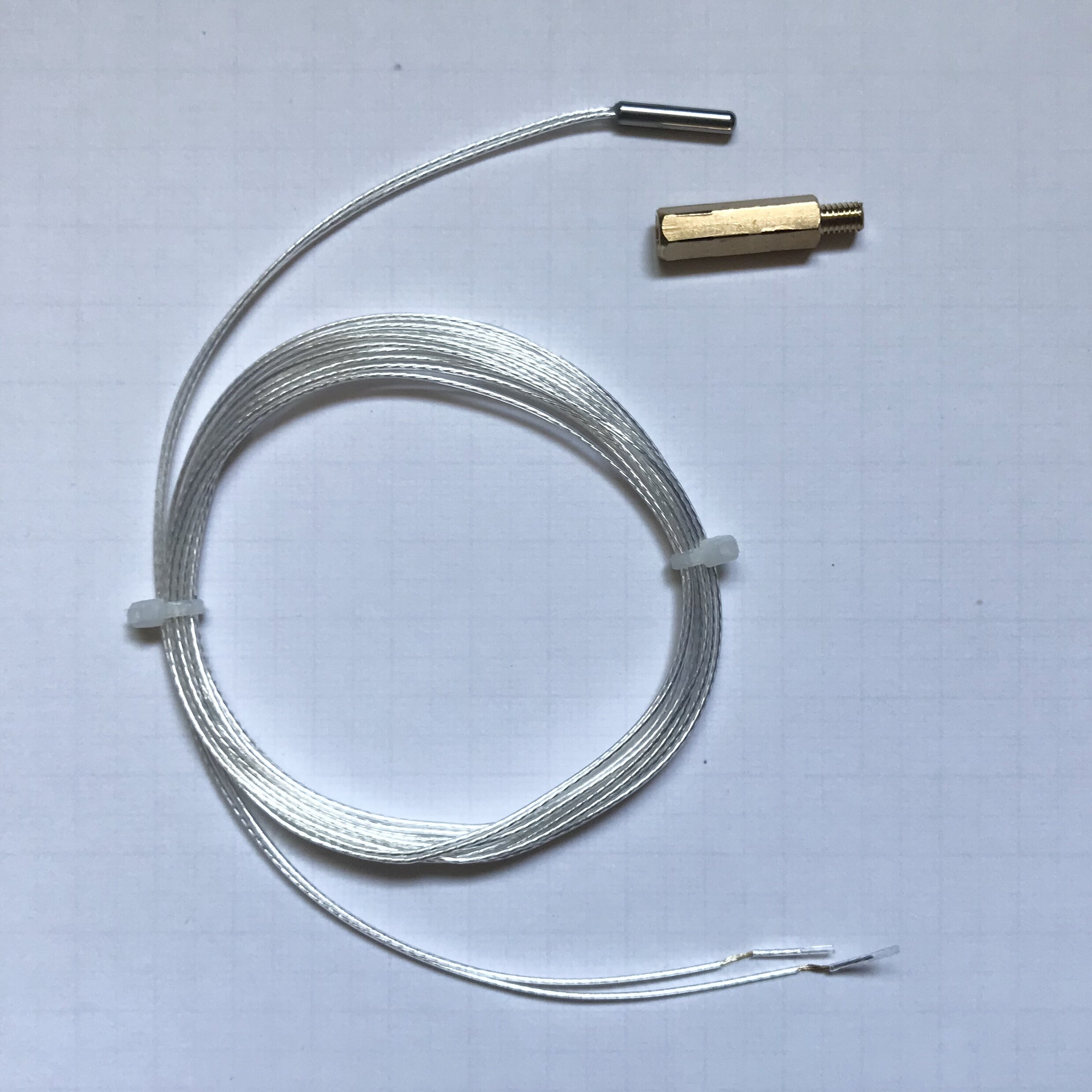
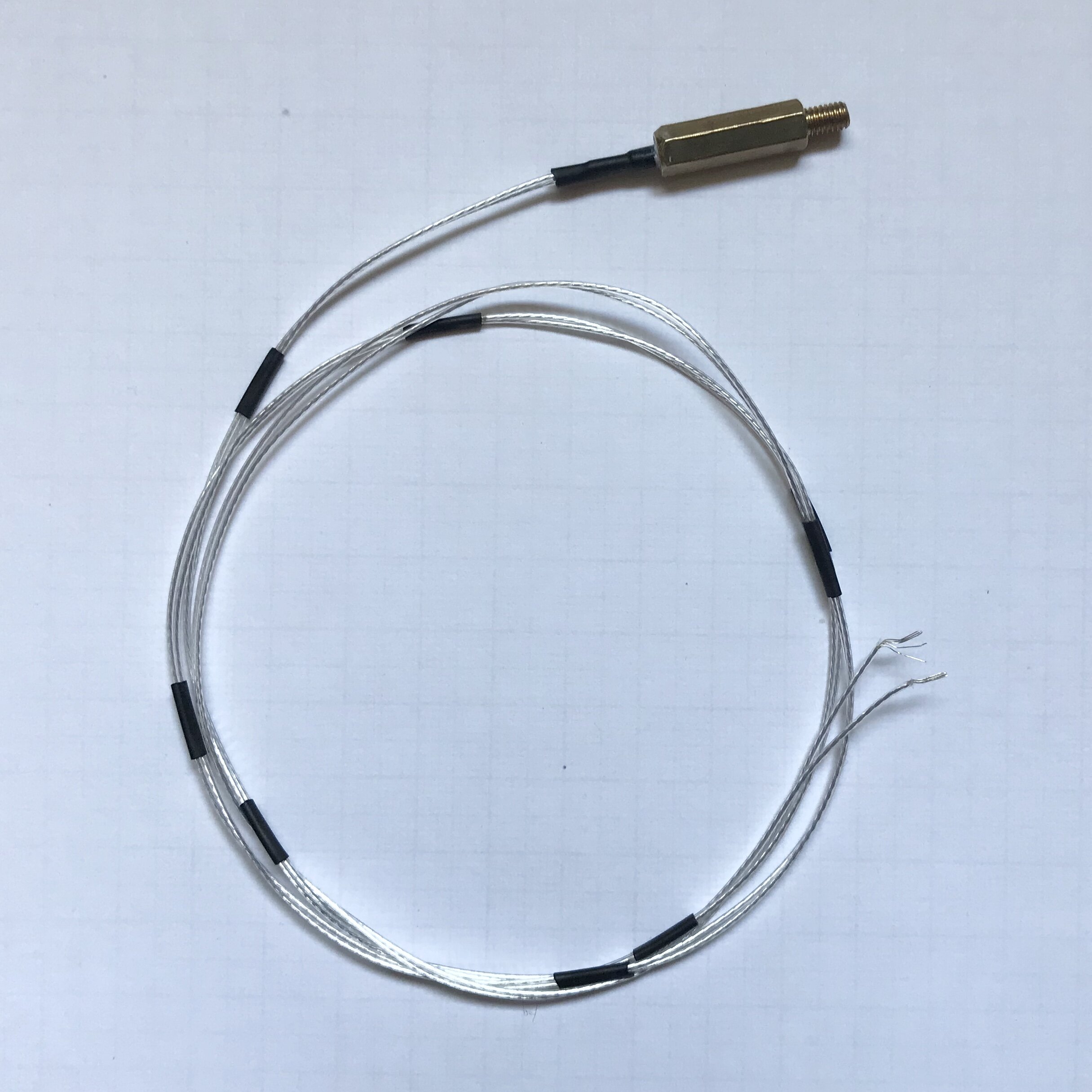
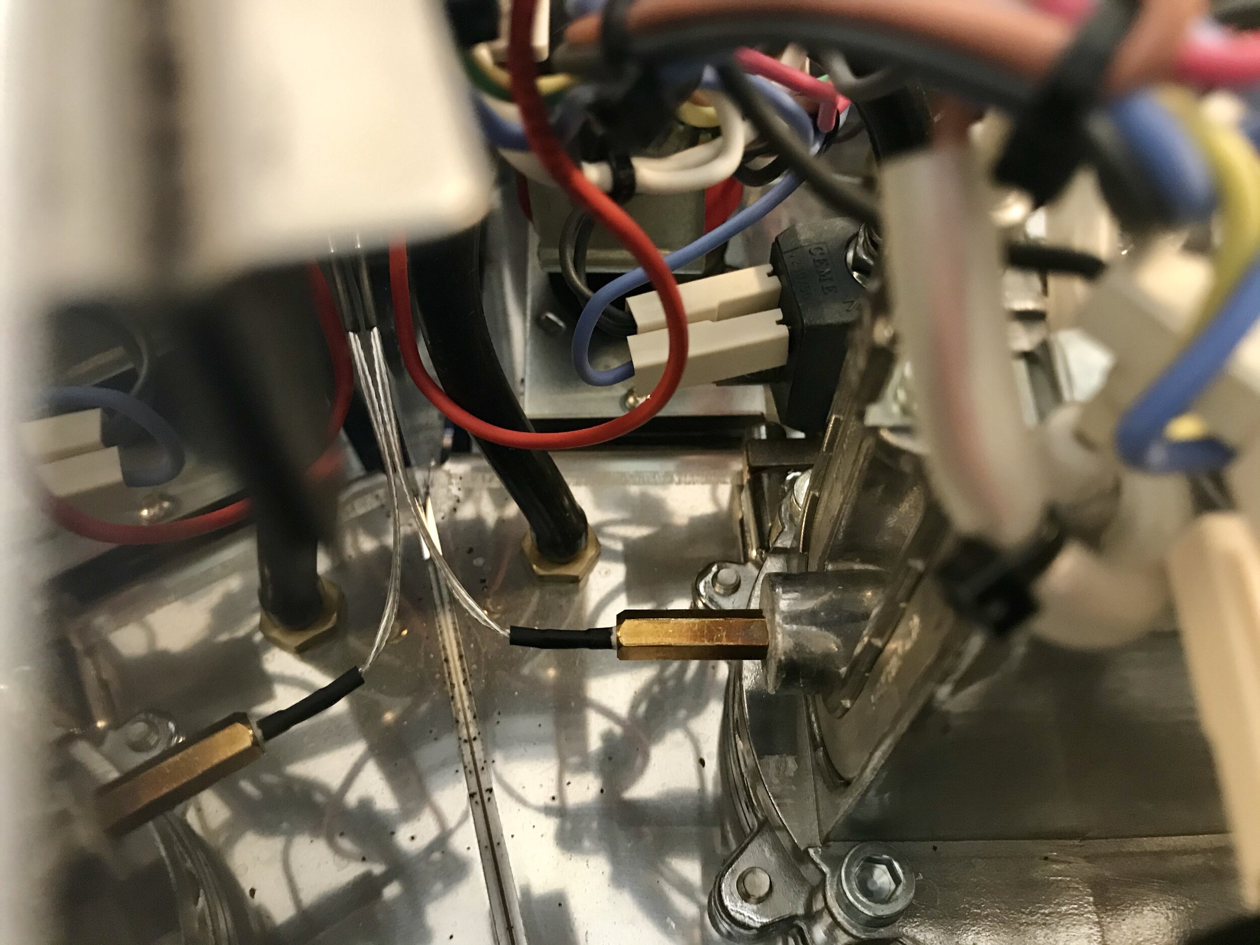
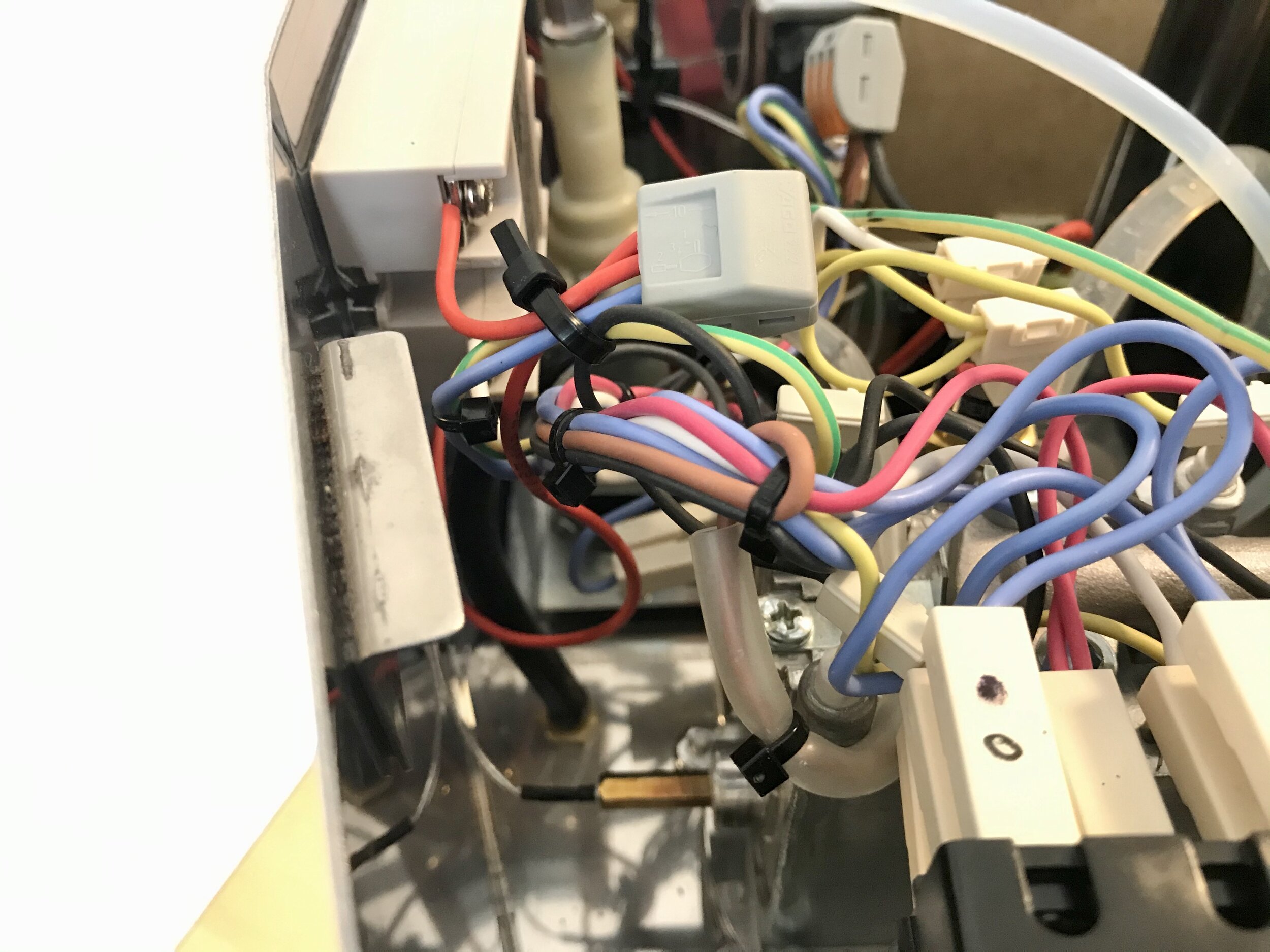
Next up: measuring the temperature. This was actually pretty hard, as I wanted it to be really precise. And as I looked around I was intrigued by the idea to have a simple replacement component for the original thermostat, which has an M4 thread. And thanks to the 3D printer world there are a lot of M4 threaded type K thermocouples out there. Unfortunately they don’t really fall in the “precise” category regarding measuring accuracy. An error of at least ±2 °C is not acceptable if you aim at .1 precision for an optimal result. There are other and better thermocouple types, but they are in bad supply and not M4 thread compatible, so I started all over. If I had started with a simple google search on “measure temperature esp8266“ I would have learned very quickly that the most accurate (and also easy and cheap) solution would be a PT100 or PT1000 thermo element. So I finally came to the MAX31865 controller and a PT1000 1/3Din (class AA) element. It is very important to choose an element with small error ratings, I also recommend small (short) elements, as they are easier to integrate. In this case the best I could find was class AA (3mm x 15mm), translating into the following error-formula:

E = 0.1 °C + 0.0017 | t | °C

So for our preferred working range around 100 °C the maximum measurement error is 0.1 °C + 0.0017 * 100 °C = 0,27 °C. As this is the max error rating, we can generally assume that the error will be much smaller in reality, especially as we don’t use the thermo element in extreme temperature ranges (mine has a measurement range of -40 °C to 400 °C). An error of around a fourth of a degree in measuring the boiler temperature actually sounds really great to me.

If you want some more details on the type k thermocouple vs. RTD (PT100 / PT1000) question, you should check this comparison.

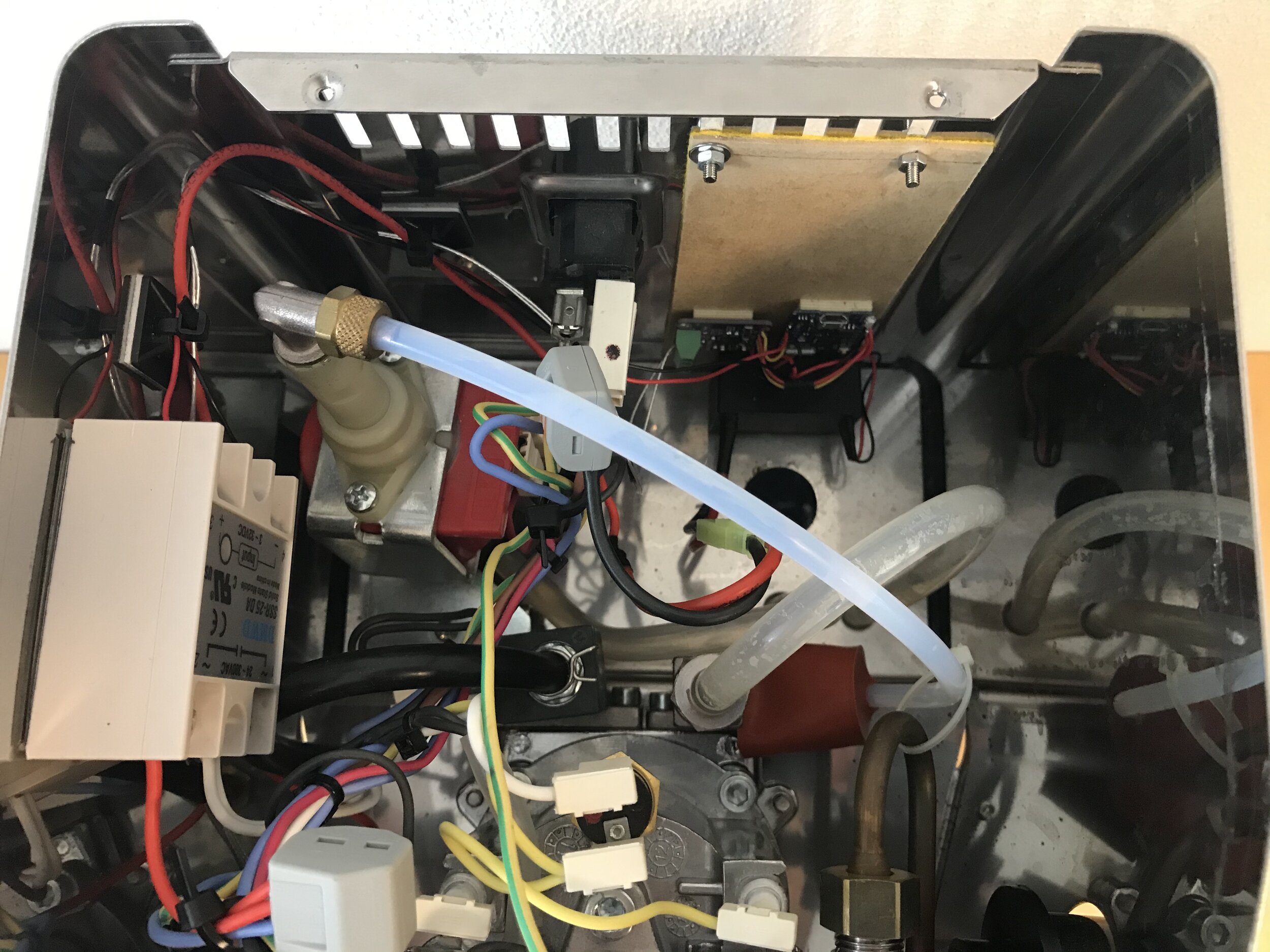
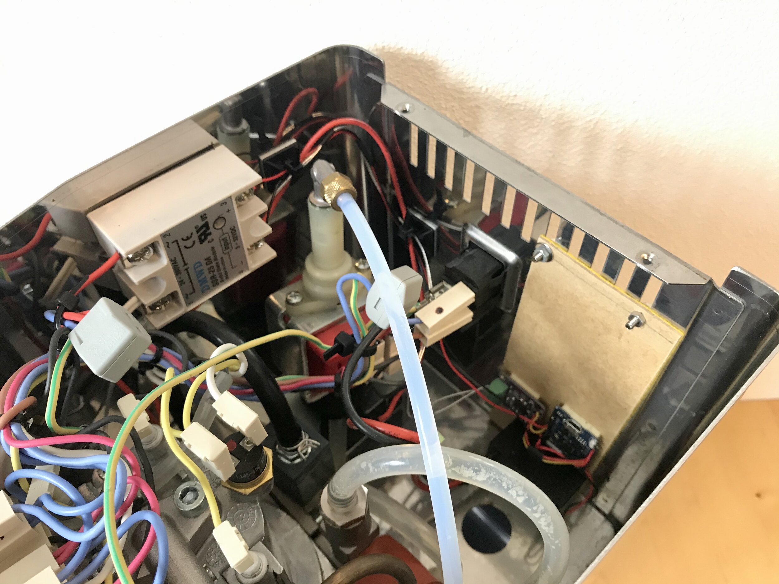
The last two components where finally pretty easy to find. Still missing are the solid state relay to control the heating and the power supply for the microcontroller. The relay has to switch 230V AC just above 5.5 Ampere, as the heater draws a lot of power. So I needed an AC solid state relay that could be switched with an 3,3V input and have a currency rating of at least 10A (better save than sorry here). I finally chose the SSR-25DA (25A AC); yes, the 10A version may also suffice, but if you own the 110V-version of this machine, you would exceed the 10A heating current. Also it is not advised to use these “cheap” SSRs close to their rated limit. And as both versions (10A vs. 25A) are around the same price and size, the choice was simple.

And lastly, an almost boring component, a simple 230V to 3,3V power brick, to power the electronics. In this case I went for a small Meanwell 8.2W print-type power supply (IRM-10-3.3). There are a lot of different models and I expect the actual power drain to less than 1W, so we are again clearly on the safe side.

So finally, all parts ordered……

And I think this is already a good introduction to the project and components I plan to use. In the next posts I will explain the other aspects of this project like the software, website and build in more detail. I hope you enjoyed reading.

P.S.:

As mentioned there are many projects like this out there, this is just my opinionated approach. I want to give you some links to sources that are related and partially inspired me to this project:

OTHER PARTS OF THIS SERIES:

Better Location Sharing with Shareloc

It's finally been done and I'm very happy to see Shareloc in the iOS App Store. The first prototype was created almost a year ago, the backend api has been rewritten 3 times and the app already shows its second redesinged UI. Overall I'm very satisfied with the current state and looking forward to push the app further.

Why yet another location sharing app?

Good question and I heard it a lot telling people about Shareloc. So I want to explain you how it all came together. In the beginning there was a simple need. I just wanted to share my location with my wife and my friends. And in this case there are not only alreadx exisiting some apps for that, it's an iOS integrated feature. So I used it and I was disappointed because it didn't work as expected. Then I tried other location sharing services on iOS including glympse, facebook and google maps. But none did satisfy all of my requirements and those are not that special in my opinion. Basically there are 3 obvious features that I want:

  • Ease of use: It has to be really easy and fast to use. If it takes me more than 5 seconds to share my location, I probably won't use the app.
  • Accuracy: The shared location should be as accurate as possible. If the person I shared my location with only knows my position up to 100 meters accurate, then location sharing looses some use cases for me.
  • Speed: The update interval for my location should not be limited. If there is a new location available, it should be available to my shared contact immediately.

And then there is a fourth and implied feature: security! It's not last because it's least important, it's here because the user can't see it. You maybe can check if the data transfer is encrypted, but you don't know how long the location data are stored and with whom they are shared.

As all services I tested did at least fail two of those features I created a small prototype testing if the GPS on the iPhone was accurate enough to fulfill my needs. As it turns out: Yes! And now here I'm presenting Shareloc the location sharing service living up to my and hopefully also your needs and expectations.

How are you making money with a free app?

In the current state: I'm not and that is fine for me. I'm a freelance software developer and Shareloc is a some kind of work sample for people who may want to hire me. Also the operating costs of Shareloc are pretty low, so don't expect the app to loose it's current "free"-pricetag.

That doesn't mean there are no plans to monetize the app at all. In the future it might be possible to buy some extra features via an in-app-purchase or make little donations, but that are still dreams of the future.

What's next?

Shareloc is working great as it is, but it is still an 1.0, and the plans for 1.x- and 2.x-versions have been around since the beginning. During the developement and beta testing I created a backlog of ideas and feature requests that I'm now prioritizing. Also if you have a feature request please use the contact form on the Shareloc website to share it with me.

Also if you like Shareloc and would like to see new features before everybody else, just let me know and I will add you as a beta tester.


Meine erste eigene iPhone (Location Sharing) App

Der Vorsatz eine eigene App im Apple Store zu haben besteht schon lange, doch irgendwie hat es bis jetzt nie geklappt. Und das obwohl ich schon 6 Jahre für die iOS Plattform programmiere. Nachdem ich inzwischen sogar selbständiger iOS Entwickler bin, konnte ich diesen Umstand so nicht belassen. Es blieb die Frage was die eigene App eigentlich machen bzw. welches Problem sie für mich, aber vor allem die Nutzer, lösen soll. Die kurze Antwort darauf ist: Location Sharing. Der primäre Grund dafür ist, dass ich mit den vorhandenen Lösungen unzufrieden war. Entweder waren diese zu umständlich, die Nutzeroberfläche nicht durchdacht, der Dienst zu langsam, ungenau oder unzuverlässig. Damit waren auch schon die Ziele der neuen App definiert: Einfach, Schnell, Präzise, Zuverlässig und da es hier um Positionsdaten von Nutzern geht, mit höchster Priorität auch Sicherheit.

Was ist dieses "Location Sharing" und wozu brauche ich es?

Mit dem Begriff "Location Sharing" wird die Möglichkeit beschrieben, den eigenen Standort mit einer anderen Person zu teilen. In der Regel wird dieser Person einfach eine Nachricht mit einem Link zu einer Webseite gesendet, über die der eigene Standort auf einer Karte angezeigt werden kann. Der Andere weiß somit wann ich mich wo befinde. Doch wozu nutze ich diese Funktion?

  • Jemanden wissen zu lassen, dass ich mich gerade auf dem Weg befinde. Egal ob der ich von der Arbeit nach Hause fahre, oder mich mit Freunden treffe.
  • Treffen ohne genauen Treff- und Zeitpunkt, wie zum Beispiel beim Shopping, in einem Park oder einem Konzert.
  • Den richtigen Weg finden. Wenn man in einer unbekannten Umgebung nicht weiter weiß, kann man einfach den Standort teilen und sich von einem Bekannten den Weg erklären lassen.

Es gibt aber viele weitere Situationen, in denen ich inzwischen gerne meinen Standort teile.

Aktueller Stand

Seit der Idee und Konzeption ist nun schon einige Zeit vergangen. Da es sich bei einem solchen Dienst nicht "einfach" nur um eine App handelt, sondern auch um einen Webservice, eine Webseite und ein paar weitere Dinge, war auch wirklich viel zu tun. Das meiste ist nun aber geschafft und ein Ende der Entwicklung in Sicht. Mit dem Ergebnis bin ich bisher sehr zufrieden, seit wenigen Monaten läuft bereits ein geschlossener Betatest des Dienstes. Entsprechend aktueller Planung wird die App im ersten Halbjahr 2017 im App Store veröffentlicht. Mehr möchte ich jetzt hier aber noch nicht verraten.

Betatester gesucht

Um die Zuverlässig- und Skalierbarkeit der App besser beurteilen zu können, benötige ich aktuell noch ein paar Betatester. Wer andere Dienste, wie das in iOS integrierte Teilen des Standortes oder Apps wie Glympse regelmäßig nutzt und daran interessiert ist meine App zu Testen, kann sich über das folgende Formular zum Betatest anmelden. Wichtig ist, dass die App nur für das iPhone gemacht ist, Nutzer eines iPads oder anderer Smartphones können diese somit aktuell nicht installieren. Nach erfolgreicher Anmeldung sende ich Dir eine TestFlight Einladung zur App, diese enthält eine Anleitung wie Du die App auf Deinem iPhone installieren kannst. Zusätzlich erhältst Du eine Einladung zu einem Slack Channel, den ich für die Kommunikation mit den Testern nutze. Dort kann man mich am einfachsten direkt erreichen, ob mit Fragen, Ideen oder Problemen.

Custom compass position in MKMapView

For map views in native iOS apps MKMapView is my first choice. While implementing an map based app I came to the point where the compass was showing under a menu component. This is because the default compass position is in the top right corner of the map view. So there were two solutions to the problem:

  1. Change the position of the compass
  2. Remove the compass and implement a custom one

Although the second option sounded tempting, the first one seemed to be the obvious choice. But then I learned that the MKMapView doesn't let you do anything with its compass besides the possibility to show or hide it via the 'showCompass' function. I was surprised by this fact, because on the iOS default map app you can see the compass on a custom position.

Custom compass position in apple maps app

Solving the puzzle

By analyzing the issue I saw the compass is a subview of the map with a custom class called 'MKCompassView'. As the class itself is private API it is not exposed for external use, but I don't need that. To set a new position for the compass I subclassed the MKMapView component and overrode the layoutSubviews function to change the frame of the MKCompassView.

As you can see this is really easy. Then I just had tell the app to use the map view subclass as the map component and my problem was solved.

 
App showing the compass at a custom position on a MKMapView
 

Make it useful

Then I realized that a static position isn't good at all in my case, you will see the reason later. So I made the position variable and added a simple animation. The final code looks like this:

Inside the app it looks like this:

 
Animated custom compass position on a MKMapView